
This post has already been read 6487 times!
The three-way ‘fridge fitted to our Morocco is an essential item, especially when it is hot outside but these absorption refrigerators do not work at their best when the ambient temperature is over about 30C. A compressor refrigerator is better for very high temperatures but it is possible to improve performance by fitting a little fan to draw air over the condenser at the back of the unit. Dometic sell a kit to do this but it costs about £50 and you can make your own for less than £10 although I spent a little more by buying a very quiet fan, but a cheaper if perhaps a little noisier fan would work just as well for cooling.
The fan is controlled by an adjustable temperature controller, which although not essential I felt it was a bit more elegant to have an adjustable controller rather than just switch the fan on and off manually when I felt we needed it, although you could certainly do this for a minimalist approach. The temperature controller I fitted was bought from the following website for the massive price of £3.29 with free postage. http://www.ebay.co.uk/itm/50-110-C-Digital-Heat-Cool-Temp-Thermostat-Temperature-Control-Switch-DC12V-New/351399680014?_trksid=p3693.c100102.m2452&_trkparms=ao=1&asc=20140212121249&meid=175a4e0473394837baacdf26e6e9c221&pid=100102&
This came within a couple of days but it was free of any instructions but a bit of Googling found another website which explains what the terminals are and how to use it. http://www.banggood.com/-50-110-DC12V-Cool-Heat-temp-Temperature-Control-Switch-p-912023.html
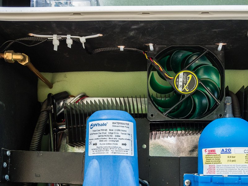
The fan I bought was this one: http://www.ebay.co.uk/itm/121552181987 You can get cheaper ones but this one is very quiet. It has three wires, the red is positive 12v, black negative and the yellow is the control wire which is not needed. It comes with a second bit of wiring which has a resistor in it to make the fan run slower and even more quietly which I modified by cutting off the resistor and using what was left as the connection to the temperature controller after pulling out the yellow wire from the plug.
The installation after I had finished looks like this: (The images should enlarge if you click on them and then press your browser’s back button to return)
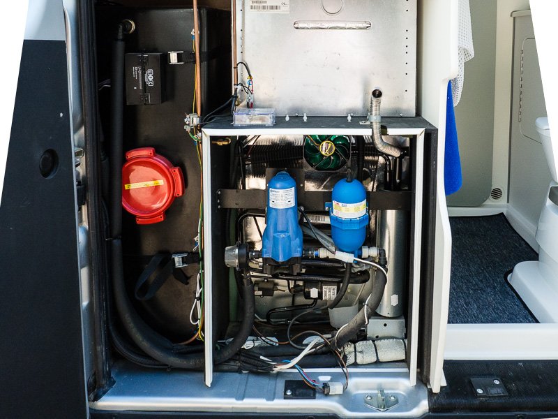
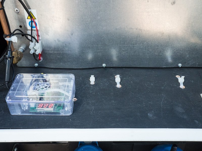
The temperature controller was fitted inside a modified Raspberry Pi case but you could use more or less anything, such as a little Tupperware box.
The fan and the Raspberry Pi box were all held in place using cable ties fitted through the plywood shelf the oven fits on. I did consider fitting the fan in the rear door behind the top vent but felt it should be more effective if it was closer to the condenser. I also positioned it so there was room for a second fan if that turned out to be needed later. The controller relay is rated at 10A so this isn’t a limiting factor in how many fans are fitted.
In the picture above the leftmost cable tie is holding the temperature sensor from the controller. The cable tie which runs transversely is securing the temperature controller and the bottom of the Raspberry Pi box.
Rather than try and draw a wiring diagram I will explain the wiring using the four terminals on the temperature controller which are marked K1, K0, +12v and GND, which you can see on one of the lower pictures here; http://www.banggood.com/-50-110-DC12V-Cool-Heat-temp-Temperature-Control-Switch-p-912023.html
The +12v terminal was connected through an in-line 1 amp fuse I bought from Halfords to a 12 volt supply I took off the back of the oven where there was a convenient terminal block I could tap into. The GND was connected to the negative wire from the cooker. If your Murvi doesn’t have an oven you will have to hunt around for a 12 volt feed.
The K0 and K1 terminals connect internally to the contacts in the relay and close when the set temperature has been reached. So to get the power to the fan I connected a loop of wire from the GND terminal to K0 and then connected the fan across the +12v and K1 terminals with the red wire going to the +12v terminal of course. This does mean the fan is permanently “live” as the switch is in the return but this was just the way it happened. It would be better to have the switch in the positive feed I think and this could be easily done. You might be able to see how it is wired in the picture below:
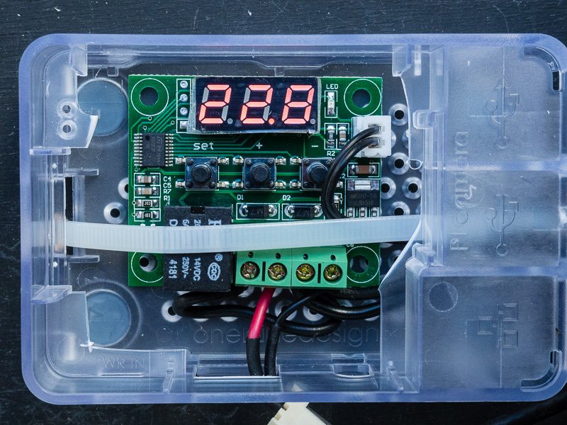
The red and black wires coming out at the bottom are the supply to the fan. The little white plug in the top right is the connection to the temperature sensor.
There are three buttons on the temperature controller. If you press once the one marked “set” the display will flash and you can then use the + and – buttons to set the temperature the fan controller will come on. I set it initially to 25C so I could test everything worked by holding the sensor in my fingers to warm it up and after seeing the fan start up I let go of the sensor and when the temperature had fallen to 23C the fan switched off. I am told the Dometic kit is set to come on at around 50C which seems high but of course a lot of heat is generated at the back of the ‘fridge. I have a thermometer which has a sensor on the end of a cable which I will do some experimenting with to determine what sort of temperatures are reached behind the ‘fridge and set the controller appropriately.
My installation isn’t perfect as the 12v feed from the oven is permanently on and is not part of the “Aux” circuit but I couldn’t find any 12v switched supply anywhere near the ‘fridge other than its own 12 volt supply which only comes on when the engine is running, which is no good when you are parked up. So at the moment the fan can only be permanently switched off by removing the fuse – which isn’t difficult to do but I need to put a switch in there somewhere.
John Laidler
checkout this post if your fridge is not cooling when on gas:
https://www.murviclub.org.uk/fridge/